- 您现在的位置:买卖IC网 > Sheet目录221 > DMS-40PC-1-RL-BCD-C (Murata Power Solutions Inc)DPM LED 2VDC 4.5DIG BCD LP RED
DMS-40PC Series
4? Digit, LED Display Digital Panel Voltmeters
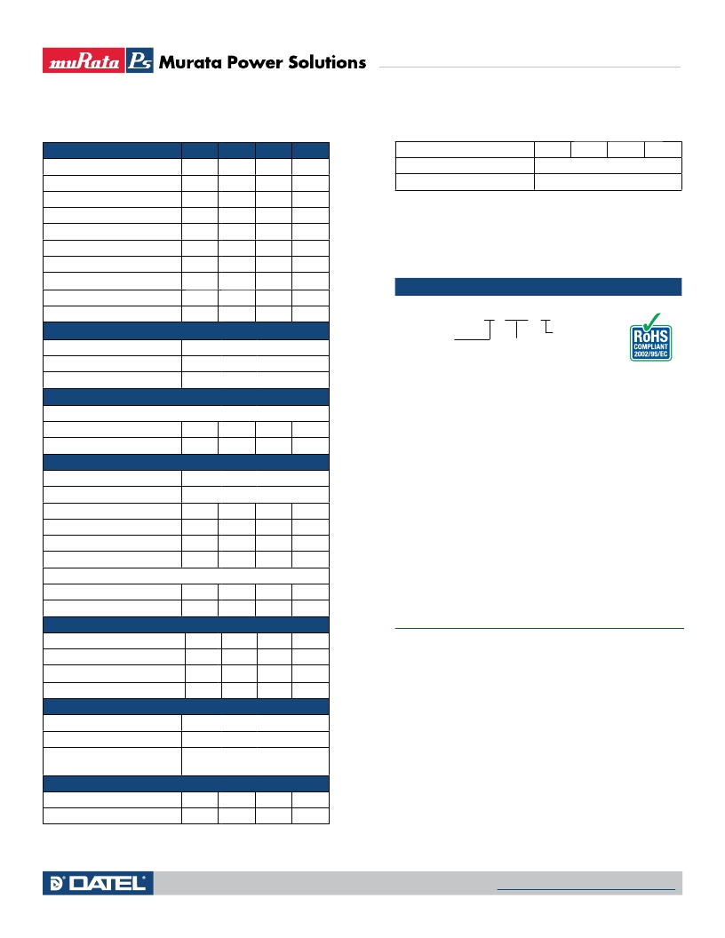
Performance/Functional Speci?cations
Typical at T A = +25°C and supply voltage = +5V using the single-ended input
circuit, unless otherwise noted.
Analog Inputs
Min.
Typ.
Max.
Units
Humidity (non-condensing)
0
–
95
%
Full Scale Input Range:
Case Material
Polycarbonate
DMS-40PC-1
–
±2
–
Volts
Weight
0.75 ounces (21 grams)
DMS-40PC-2
DMS-40PC-3
Input Impedence:
DMS-40PC-1
DMS-40PC-2, -3
Overvoltage Protection ?
Common Mode Voltage Range
CMRR (dc to 60Hz)
–
–
–
100
0.8
–
–
–
±20
±200
1000
1
–
–
86
–
–
–
–
±250
±2
–
Volts
Volts
MΩ
MΩ
Volts
Volts
dB
? Applies for transient or continuous overvoltages applied to (+) INPUT HI (pin 11) with (–)
INPUT LO (pin 12) properly connected. Pin 12 is not overvoltage protected (see Figure 1).
Voltages applied to pin 12 should not exceed the supply voltage.
? See Technical Notes.
? BCD outputs are optional and must be speci?ed in the part number.
See Ordering Information.
? Includes high-intensity and BCD-output models.
Ordering Information
DMS-40PC - 1 - R S - C
Control Inputs ?
Decimal Pt. Placement (Pins 4-6, 8)
Display Test (Pin 2)
Display Hold (Pin 9)
Tie to pin 3 to activat e
Tie to pin 3 to activate all segments
Tie to pin 3 to hold last reading
Input Range:
1 = ±2V
2 = ±20V
3 = ±200V
Add -C for RoHS
LED Color:
GS = Standard Green
RH = High-Intensity Red
RL = Low-Power Red
BCD Outputs ?
Logic Levels (1 LSTTL load max.):
BCD Output Models :
RS = Standard Red
YS = Standard Yellow
Logic “1”
Logic “2”
+2.4
–
–
+0.4
–
+0.8
Volts
Volts
BCD outputs are only available on the following red meters.
DMS-40PC-1-RS-BCD-C for ±2V input range
DMS-40PC-2-RS-BCD-C for ±20V input range
Performance
DMS-40PC-3-RS-BCD-C for ±200V input range
Sampling Rate
Accuracy (3 minute warm-up):
2.5 reading per secon d
DMS-40PC-1-RL-BCD-C for ±2V input range
DMS-40PC-2-RL-BCD-C for ±20V input range
DMS-40PC-3-RL-BCD-C for ±200V input range
DMS-40PC-1 (Vin = +1.9V)
–
±2
±3
Counts
Accessories:
DMS-40PC-2 (Vin = +19V)
DMS-40PC-3 (Vin = +190V)
Zero Reading (Vin = 0 Volts)
–
–
“–001”
±3
±3
“000”
±4
±4
“001”
Counts
Counts
DMS-30-CP
DMS-BZL1-C
DMS-BZL2-C
DMS-EB-C
Panel cutout punch
DMS-40 bezel assembly
DMS-40 bezel assembly with sealing gasket
Application/evaluation board with standard
MOLEX connector, decimal point solder pads
Temperature Drift (0 = +50°C)
and attenuation resistor pads.
DMS-40PC-1
DMS-40PC-2, -3
–
–
±0.4
±0.4
±1
±1.5
Cnts/°C
Cnts/°C
A panel-mount retaining clip is supplied with each model.
Power Supply Requirements
TECHNICAL NOTES
Supply Voltage
+4.75
+5.00
+5.25
Volts
1. ANALOG COMMON (Pin 10) : This pin is an internal, low-noise
Supply Current:
ground for the DMS-40PC. It is internally connected to pin 3
Standard Models ?
Low-Power Models
–
–
+100
+35
+140
+50
mA
mA
(5V RETURN). Do not connect pin 10 to either pin 3 or your system
ground as this will create a ground loop and possibly result in errone-
ous readings.
Display
2. REFERENCE INPUT/OUTPUT (Pin 7) : This pin accesses the meter’s
Display Type and Size
Polarity Indication
Overrange Indication
4? digit, 0.52"/13.2mm high LED
Autopolarity ("–" for negative Vin)
"–0000" (?ashing) for negative Vin
internal reference and is used during the factory calibration proce-
dure. Pin 7 should be left open in most common applications. It can
be used in certain “ratiometric” applications in which it is desirable
Physical/Environmental
"0000" (?ashing) for positive Vin
for the meter’s reference to track an external reference. See Ap Note
3 in the DATEL Panel Meter Catalog for more details.
Operating Temperature
Storage Temperature
0
–20
–
–
+50
+75
°C
°C
3. DISPLAY TEST (Pin 2) : Connecting pin 2 to ground (pin 3, 5V
RETURN) will activate all LED segments, and the display will read
“–18888” regardless of the actual applied input. To reduce self-heat-
ing, the display should not be left in the “test” mode for more than 10
seconds. This pin should be left open if unused.
www.murata-ps.com/support
09/27/11
MPM_DMS-40PC.C06 Page 2 of 6
发布紧急采购,3分钟左右您将得到回复。
相关PDF资料
DMS-40PC-4/20S-24RS-I-C
METER DISP LED 4.5DIG 24V RED
DMU-30ACV-1-DR-C
VOLT METER LED 200ACV 0.1V RED
DMU-30DCV-2-DR-C
VOLT METER LED 20DCV 0.01V RED
DN-91648U
PATCH PANEL 19" 48PORT RJ45 CAT6
DPM125L
METER DPM LCD3.5DIGIT 200MV BKLT
DPM1AS-BL
LCD 5.5MM UNIV MINI METER BK LIT
DPM2000S
LCD DPM 5V/200MV 3.5 DIG S-RAIL
DPM2AS-BL
LCD 8.25MM UNIV MINI METR BK LIT
相关代理商/技术参数
DMS-40PC-1-RL-C
功能描述:数字面板表 4.5 Digit +-2V Input Low Power Red RoHS:否 制造商:Murata Power Solutions 设备类型:AC Voltmeters 显示器类型:LED, 3 Digit, Red 工作电源电压:85 VAC to 264 VAC 工作电源电流:50 mArms 输入电流:50 mA 输入频率: 输入电压:120 VAC 系列:DMS-20PC-1-LM
DMS-40PC-1-RS
功能描述:数字面板表 4.5 Digit +-2V Input Std Red RoHS:否 制造商:Murata Power Solutions 设备类型:AC Voltmeters 显示器类型:LED, 3 Digit, Red 工作电源电压:85 VAC to 264 VAC 工作电源电流:50 mArms 输入电流:50 mA 输入频率: 输入电压:120 VAC 系列:DMS-20PC-1-LM
DMS-40PC-1-RS-BCD
功能描述:数字面板表 4.5 Digit +-2V Input Std Red RoHS:否 制造商:Murata Power Solutions 设备类型:AC Voltmeters 显示器类型:LED, 3 Digit, Red 工作电源电压:85 VAC to 264 VAC 工作电源电流:50 mArms 输入电流:50 mA 输入频率: 输入电压:120 VAC 系列:DMS-20PC-1-LM
DMS-40PC-1-RS-BCD-C
功能描述:数字面板表 4.5 Digit +-2V Input Std Red RoHS:否 制造商:Murata Power Solutions 设备类型:AC Voltmeters 显示器类型:LED, 3 Digit, Red 工作电源电压:85 VAC to 264 VAC 工作电源电流:50 mArms 输入电流:50 mA 输入频率: 输入电压:120 VAC 系列:DMS-20PC-1-LM
DMS-40PC-1-RS-C
功能描述:数字面板表 4.5 Digit +-2V Input Std Red RoHS:否 制造商:Murata Power Solutions 设备类型:AC Voltmeters 显示器类型:LED, 3 Digit, Red 工作电源电压:85 VAC to 264 VAC 工作电源电流:50 mArms 输入电流:50 mA 输入频率: 输入电压:120 VAC 系列:DMS-20PC-1-LM
DMS-40PC-1-YS
功能描述:数字面板表 4.5 Digit +-2V Input Std Yellow RoHS:否 制造商:Murata Power Solutions 设备类型:AC Voltmeters 显示器类型:LED, 3 Digit, Red 工作电源电压:85 VAC to 264 VAC 工作电源电流:50 mArms 输入电流:50 mA 输入频率: 输入电压:120 VAC 系列:DMS-20PC-1-LM
DMS-40PC-1-YS-C
功能描述:数字面板表 4.5 Digit +-2V Input Std Yellow RoHS:否 制造商:Murata Power Solutions 设备类型:AC Voltmeters 显示器类型:LED, 3 Digit, Red 工作电源电压:85 VAC to 264 VAC 工作电源电流:50 mArms 输入电流:50 mA 输入频率: 输入电压:120 VAC 系列:DMS-20PC-1-LM
DMS-40PC-2
制造商:未知厂家 制造商全称:未知厂家 功能描述:4 1/2Digit, LED Display Precision, Miniature Digital Panel Voltmeters